
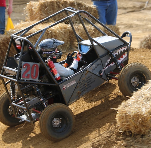
Suspension & Steering
Project Design/Motivation
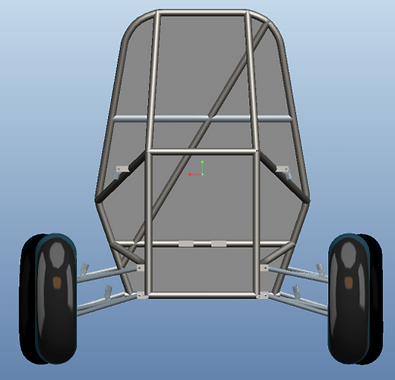
This teams mission is to develop the suspension and steering system for the SAE Baja car such that the car handles well and is sufficiently robust to complete the demanding dynamic events.
Conceptual Designs
Steering
The steering aspect within the BAJA vehicle is vital. This connects the driver to the suspension system and ensures that the vehicle is easy to control. The rack and pinion/tire rods/and steering arm were all designed, specked, and analyzed using SolidWorks to ensure that the system would behave accordingly. Consequently, the parts were ordered according to our calculations and assembled to our team vehicle.

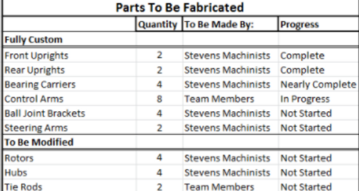
Rear Uprights
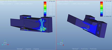
The design of the rear uprights was dependent on several factors such as caliper position, bearing size, and suspension geometry. Pictured right is an initial design, while below the final design can be seen undergoing stress analysis in the technical section. The driving factors that led to design changes were control arm attachment joints, caliper location and manufacturing techniques. There was also a reduction of thickness, which decreased the weight while maintaining performance.

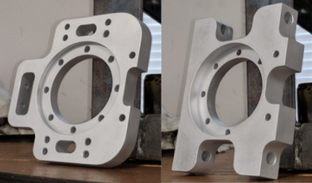
Front Uprights
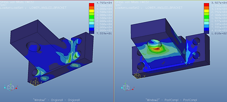
The front uprights are very similar in purpose to the design of the rear uprights; however, they differ in that the front uprights must also account for a steering system. Thus they must use ball joints to attach to the control arms and must have a linkage connection to allow the vehicle to turn. Finalized designs can be seen to the right. Similar design considerations were made for durability, weight reduction, and parts fit.
Control Arms

The control arms were designed with the system dynamics in mind. Their lengths were determined using dynamic modeling to achieve a suspension that held the car at a desirable ride height while minimizing roll during cornering. The front suspension features control arms that attach to ball joints while the rear suspension features control arms that attach to bushings.


Technical Analysis


Front Uprights
Stress simulations in Creo Mechanica were used to iteratively optimize the design of the uprights to reduce weight where possible, while maintaining structure and robustness for long-term use. The same load cases were applied to the front and rear uprights, as all wheels are likely to encounter the same forces over rough terrain.
Rear Uprights

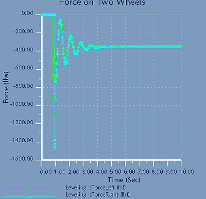
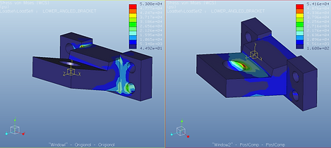
The rear uprights were modeled in Creo 3D Parametric Software and analyzed for different load cases we expect to see on the track, such as impact and cornering loads. The team arrived at the assumed load values by assuming parameters values such as the weight of the vehicle and the coefficient of friction (track). The the stress contour plot below depicts the stress in the upright at any given point, and is summarized in the table following the plot.


Control Arms
The diameters of the control arms were selected using static modeling of a worst case scenario on one of the sprung uprights. The static model showed that in a simulated impact capable of fully compressing the spring, the control arms would not fail if they were constructed from tubing larger than 0.5 inches in outer diameter. For safety, the tubing selected was 7/8" with a wall thickness of 0.12" .

Check the front, side and rear views of the car!


Cornering
Check out this awesome simulation playback of the car in cornering!
Phase Five Updates
Phase Five Updates
Phase Five Updates

Technical Design


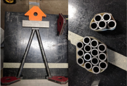
Fabrication


Phase Six Updates - We made it!


Phase six was a wild ride. It began with a rapid dash to the finish with expeditious fabrication and on-the-spot designing. In the end, we made it to competition and solidified the idea that the SAE collegiate design series can be done in a one year format at Stevens. This was truly a win for the university. No doubt, the powers that be will be so impressed by the success of this year's team that they will continue to support the efforts of SAE Baja by increasing funding, reducing regulations on funding utilization and providing easier access to tools required for fabrication.
While our vehicle performed well, there was a break in one of our components in hour 4 of the endurance race. The fracture shown above sparked a wave of analysis that attempted to determine quantitatively the true cause of failure. Some suggested points of investigation were the sharp corners that could've been filleted and their associated stress concentraters as well as the material choice of aluminum. After dynamic simulations to better estimate the load cases, and static simulations to assess the damage in different load cases, the results are inconclusive. Basically, the part as designed shouldn't have broken in the way that it did under any reasonable-to-assume load. After the fact, we found out from the machinists that the parts may not have been made out of Al-6061. In fact we don;t actually know what alloy the material was made out of. For this reason we actually are able to learn very little from this fracture.
For next year, the recommendation is to add fillets to corners where possible and design fixtures to take 3x the weight of the vehicle, not 2x like we did.
Overall, the project's biggest success is the ground work laid for next year's team! With the start we gave them, next year's team should easily be able to crack top 50 at competition. We can't wait to see their results.
What a year! - All done :)
