
Powertrain
Project Design
The team's goal was to create a modular powertrain system that can be adapted to any frame design and suspension geometry. This powertrain system was integrated into the Stevens Baja car that was driven at the SAE Competition in Maryland on April 19, 2018. The team also designed a custom gearbox that was 3D printed out of ABS Plastic.
Engine Cradle
Conceptual Design
For the modular system, the team designed a cradle that contained the Briggs & Stratton engine, CVtech CVT, and Dana H12 gearbox. To ensure adaptation to any frame design, the cradle system required only four mounting locations- two in front of the cradle on the same frame member, and two behind the cradle on the same frame member. This requires, at most, the addition of two frame members to install the engine cradle.


Technical Analysis
The engine cradle will be subject to loads cause by the gearbox output, belt tension on both sides of the CVT, and weight caused by all components of the system. These loads have been represented in the table below and the locations they are applied can be seen in the following figure.

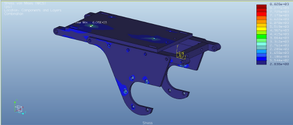
The applied loads were simulated in Creo Mechanica to establish the maximum stress and deformation in the cradle. The figure below contains the simulation results for the stress within the engine cradle.
The following figure is the simulation results for the deformation within our engine cradle.
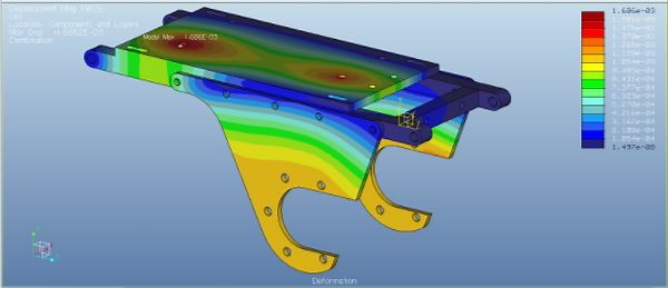
After evaluation of the simulation results, the team was able to determine the maximum deformation and stress values, as well as their locations as tabulated below.

With deformation undetected by the naked eye, and a relatively low maximum stress, the team next compared the maximum stress against the yield strength of 6061 Aluminum (the chosen material).

It was determined that at a peak stress of 6,015 psi, the team achieves a factor of safety of 5.82. This design cushion allows the vehicle to remain successful despite experiencing any unexpected dynamic loads that were not directly accounted for in simulations.
Prototype Design Overview
The team placed the engine cradle through rigorous simulations in order to establish a light weight and manufacturable design. The team also wanted to create a unit that could be easily modified to accommodate any engine, CVT, or gearbox. This was achieved by creating the following parts and providing a simple design that can be altered for years to come.
First, is the cradle subframe which is the main attachment of all other components to the vehicle frame. The team is going to use 3/4" square 6061 aluminum stock. The cross members will be welded to the main members in order to stop rotation of the cross members, and to provide access to other features since there is a tensioning mechanism integrated into one of the cross members.

Engine Cradle Subframe
The 2nd component of the engine cradle is the top plate, this will be responsible for mounting the engine to the subframe in such a way that there is adjustment to tension the CVT belt. This plate had interference issues in which a recess was required to contain the hex nut to avoid hitting the subframe. This plate will be made of a 3/8" thick 6061 aluminum plate. The tensioning mechanism will also attach to the top plate. This will give us a means of locking the tension at a desired position on the fly.
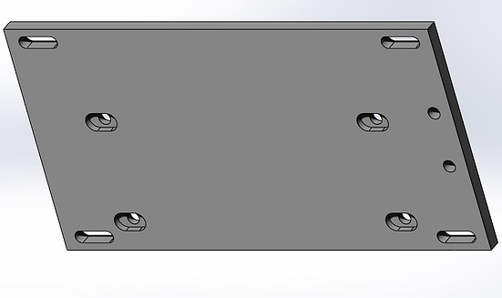
Engine Cradle Top Plate
The cradle side plate is next; this part is responsible for mounting the chosen gearbox to the engine subframe. The shape of this design is crucial because it is shaped and orients the gearbox in such a way that the CVT does not contact any parts of the engine cradle. There will be two of these plates, one on either side of the gearbox. The plates will be machined from 1/4" thick 6061 Aluminum.
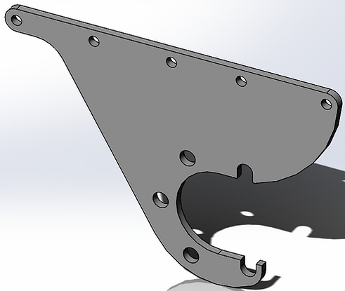
Engine Cradle Side Plate
The final component of the engine cradle is the tensioning mechanism. This mechanism was integrated to allow precise tensioning of the CVT belt. The belt driven CVT is very sensitive to belt tension and the team wanted to have precise control over this to allow for fine tuning. The mechanism is integrated into the top plate and subframe; with a piece of angle iron and hardware to provide the horizontal force which will tension the belt.

Engine Cradle Tensioning Mechanism
Fabrication Status
The team has completed the design process, drawings have created, and sent to the machine shop. As of February 21, the cradle side plates have been CNCed and the cradle top plate is in queue for machining. The cradle subframe and tensioning mechanism are on hold until the machined plates are completed; the team decided on this method to ensure the bolt patterns on the plates line up with the holes on the subframe. Although, it is expected for the holes to be aligned, within a tolerance, the team would rather create the subframe with plates in hand to ensure a perfect pattern line up; with a tight timeline and little budget room for mistakes, the team does not want to be out weeks when it would takes a day to fabricate the subframe with parts in hand.
An image of the machined Cradle Side Plate is seen below. The team decided to have this piece machined because of the complex geometry of the piece. The crucial shape is necessary to avoid the CVT when assembled. The design was further complicated once the CNC process was approved in order to reduce weight and add aesthetic appeal.
The final cradle design, engine and Dana H12 gearbox was assembled and integrated into the car as shown below.

CNCed Engine Cradle Side Plate

Gearbox
Conceptual Design
MATLAB Performance Calculator
The overall vehicle performance was assessed using MATLAB which calculated parameters such as vehicle weight, tire sizes, frictional losses in the system, effective gear ratios of the CVT, desired final drive ratio, and projected frontal area.
Two MATLAB codes, titled Full CVT and Dana, analyzed the performance of the two gearbox options for design and competition- the custom FNR gearbox and the Dana H12, respectively. The difference between the two gearboxes was the calculated final drive ratio. Namely, the Full CVT code yielded a final drive ratio of 16.5:1 whereas the Dana code yielded a final drive ratio of 13.25:1. This difference indicates that a higher top speed can be achieved with the Dana H12 gearbox, but at the cost of acceleration. One of the graphical outputs from the Full CVT code below, shows the tractive force versus road speed graph.
Microsoft Excel Gear Stress Calculator
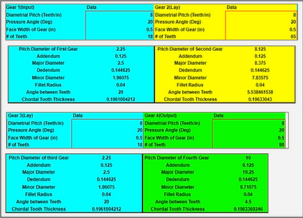
In order to further analyze the custom gearbox option, a calculator created with Microsoft Excel was created to finalize the gear ratios of each reduction set. The calculator takes into account all the design considerations of each gear such as material, load and wear factors, angular speed, torque, gear sizes, number of teeth, and diametrical pitch. The largest problem the team encountered was finding a gear material that is readily available, lightweight, and have a high enough yield strength to handle the large amount of toque expected to be produced by the gearbox. A heated treated, 4140 Steel was selected because it has a high yield strength (238 kpsi), which allowed the factor of safety to be greater than 2 for all gears in the gearbox. The calculated amount over the designated factor of safety of 2 for each gear is tabulated in the table below.
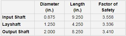
The gear calculators also provided valuable data on the amount of force each shaft in the gearbox would experience. The reaction forces were calculated and are shown in the table below and will be used to determine the minimum shaft diameters of the lay and output shafts in the gearbox. The input is constrained to a ⅞” shaft size because it needs to mate with the CVT output shaft which has a ⅞” inside diameter.
The Microsoft Excel calculator also calculated each gear's critical dimensions as shown in the figure below.
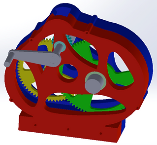
These dimensions were then used to model the gears in Creo, as seen below.
Using the forces generated from gear to gear contact to create reactionary forces on the bearings.These shear forces created Moment and Shear Graphs to analysis where the highest moments were on each of the Input, Lay, and Output shafts. The torque transmission through each shaft was also graphed. These graphs allowed valuable data to be used in determining the shaft diameter and the factor of safety for each of the three shafts
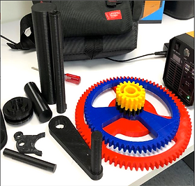
All internal components (gears, bearings, shafts, and shifter mechanism) have been designed and modeled in Creo. The prototype gearbox was 3D printed using a personal printer, owned by a SAE club member; this will significantly cut costs. The 3D print material will be ABS Plastic for the gears and shafts. Because of lack of time and material, the gearbox casing was made of Aluminum sheet metal and bolted together. The final prototype (seen below) was presented at the Stevens Innovation Expo on May 2, 2018.


Fabrication Status


Bearings and Seals
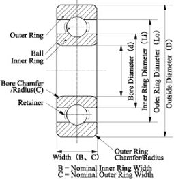
There are many different variables that will go into determining which bearings will be right for this application. The main components that determine proper bearing sizing are bore diameter, width, and outside diameter. These dimensions can be seen in the figure below:
After determining the parts of the bearing that will not vary, for instance the bore diameter, the team will be able to calculate which width and outside diameter bearings will work best for the designed gearbox. This will take into account forces on the bearings as well as RPM capabilities. Until these dimensions are determined, a general model of a bearing was designed to be easily added into existing gearbox models
Keyways
To properly determine if the standard size of the keyways would be sufficient hand calculations associated with torque, shear stress, and factor of safety were done. The following equations were used:
Torque was calculated based on the expected output from the gears and then used in a shear stress calculation. The shear stress calculation above takes into account torque, width, length, shaft diameter, number of keys and a service factor, Ks. The service factor serves as a means to determine and calculate for key fitment, whether the key is a tight fit or slide fit. After applying the groups data, the calculations were as follows.


Custom Shift Mechanism
A design for the gearbox was implemented where two selector gears that were kept stationary would be added to the gearbox. A collar and shift fork were designed to transfer load from from the input shaft to the desired gear. The gears would be slotted to fit the collar that had knobs on either side. This collar would move back and forth engaging one of the gears or neither in the case of neutral, as seen below.
Each gear would have slightly longer slots than that of the collar. This would allow the gears to be selected even when in motion, giving leeway to the engaging process. Once the collar and gear are engaged, load would be transferred from the input shaft to the gear. To accomplish this, the collar would be keyed to the input shaft and rotate with it.

CV Axles
Conceptual Design

The SAE club purchased a Dana H12 gearbox that came with standard axle half shafts that had splines that matched the gearbox. Consulting with the Suspension & Steering senior design team, the desired axle extension length was 6 inches. Although the Dana gearbox and the axle shafts were originally designed for a golf cart, the team deemed modifying the axles feasible. It was decided to utilize the “Slash Cut Method” which consists of cutting the middle column at a 45 degree angle and welding an insert in between the two severed parts.
Technical Analysis


From calculations, the output torque from the gearbox was 911.1 N-m. Running a stress simulation with this torque yielded the following stress and displacement plots:
The maximum stress was far below the elastic modulus of steel and so no permanent deformation is expected to occur.
The team is going ahead with the "Slash-Cut" method that was introduced before. The angle of cut (45 degrees) was chosen to maximize the weld surface while still keeping the thickness of the insert. The cut will be done using a metal-cutting bandsaw. The inert will be made of solid 4340 Steel. The team has already purchased the tubing and is ready to cut the axles. To ensure the shafts are welded straight, the shafts will be centered by welding in an angle iron channel.
The team will butt weld the insert to the axles shafts. To achieve a good quality weld, the end surfaces of the parts to be welded will be beveled to enable the weld material to adhere to the full thickness of the tubing and ensure mechanical continuity. The bevel angle is a function of the thickness of the parts to be welded. Common bevel angles for a thickness of 0.188 inches- according to Protem USA - are 60 and 75 degrees. The team will use an angle grinder to achieve this. The welding will be done using a TIG welder with ER70S-6 filler.
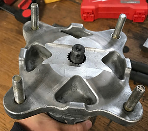
To further incorporate the current CV axles to the team design, the Powertrain team has suggested to the Suspension team to modifying the wheel hubs. Currently, the spline shaft that is being inserted into the hub is too short, not allowing room to screw on the locking hex nut and insert the pin. The Powertrain team suggested that the Suspension team should machine a step into the bore of the hub at the location shown by arrows in the following figure.
Axle shafts were cut and welded, and the hubs were machined.
All components were then integrated into the Baja car.


Fabrication Status


Finger Guards
Conceptual Design
The team’s chosen concept for a powertrain safety guard is shown below (left) as a Creo model of a steel sheet metal housing with mesh cover. (The entire powertrain system excluding the axles are shown in this figure). The finalized safety guard installed on the Baja car is shown on the right. The mesh cover was replaced with a clear cover to be able to see the CVT inside better.


Fuel Mounting & Spill Shield
Conceptual Design
The team will design a spill shield and fuel tank mounting system in accordance with the 2018 Baja SAE Rules. These rules provide guidelines for fuel tank mounting, fuel line, and spill shield designs. This spill shield will direct spilled fuel in one direction to the far back-corner of the car, away from the engine and exhaust systems underneath. Fuel can get spilled from:
-
A broken fuel line
-
Hasty refueling
-
Missing fuel cap
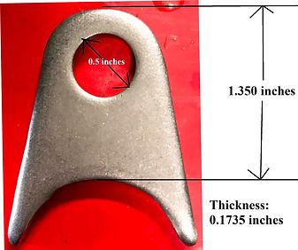
The team plans to utilize 2024 aluminum sheet metal (of 0.02” thickness) as the spill shield. The sheet metal will be bolted to tabs (as shown below) that are welded directly to the frame.
Secondary members will be welded to the frame in a T-shape and the fuel tank will be mounted to angle iron mountings that are welded to center member as shown below. A Creo model of the angle iron mountings and the fuel tank is seen below. In addition, the fuel line will be directed through a grommeted hole in the spill shield to the engine below.
All materials were purchased from McMaster and assembled in school. The team used a metal-cutting bandsaw and hand tools to cut and shape the sheet metal to the proposed design. In addition holes will be cut using a drill press. Lastly, rubber edging was used to eliminate sharp corners. The final spill shield design installed on the Baja can be seen below.


Fabrication Status
